Visit the shop to buy this issue’s print edition or poster!

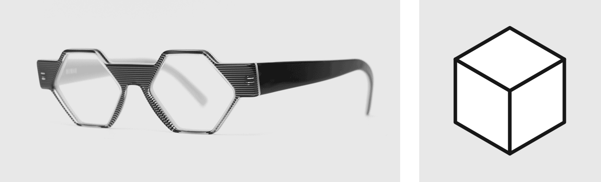
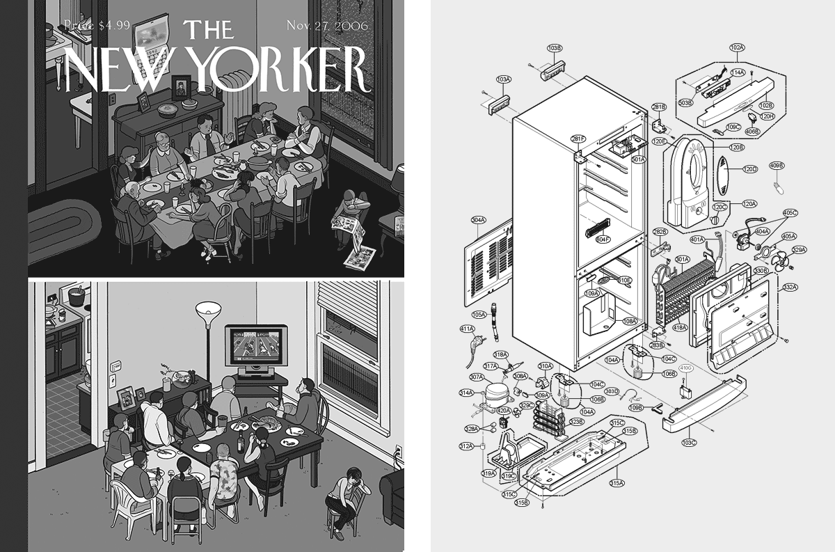
I made some changes to my look this year. My large signature beard isn’t so large anymore, I’m wearing more colors, and most recently, my new glasses are introducing new angles to my face (Fig. 1). The hexagons now framing my vision are a constant reminder of the isometric cube, whose contours are bounded by a hexagon (Fig. 2). Regular readers may recall that one of the seeds for Plus Equals was planted a few years ago with Incomplete Open Cubes Revisited, my extension of a Sol LeWitt work. I learned a lot about isometric projection from that project, but my affection for the concept didn’t begin there. Whether I’m looking at a Chris Ware illustration (Fig. 3) or an exploded-view technical drawing of a complex machine (Fig. 4), an isometric rendering always stirs something in me.
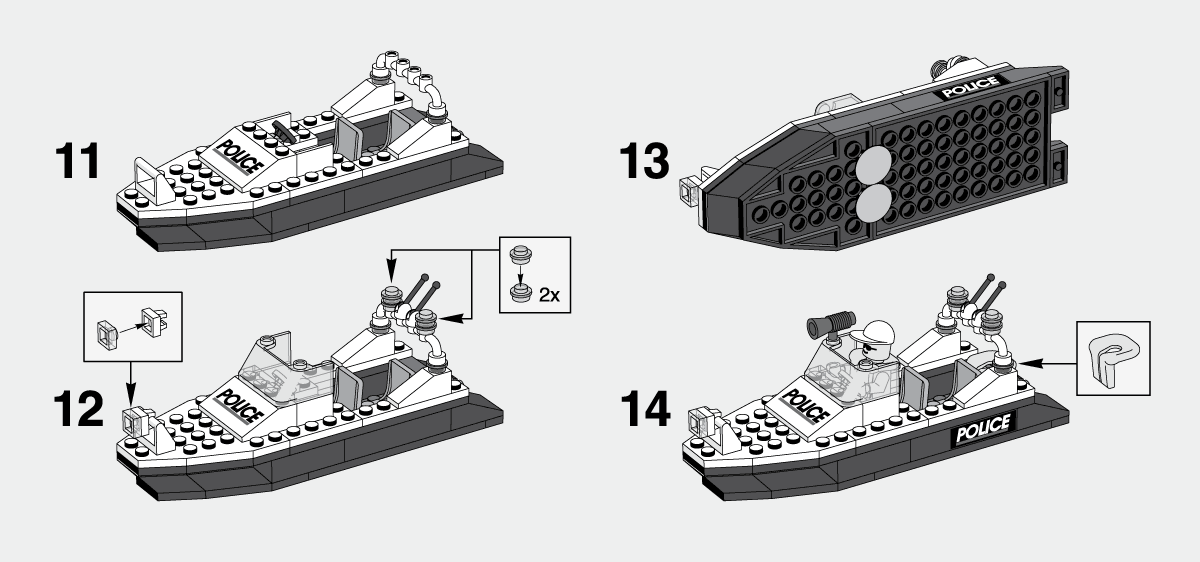
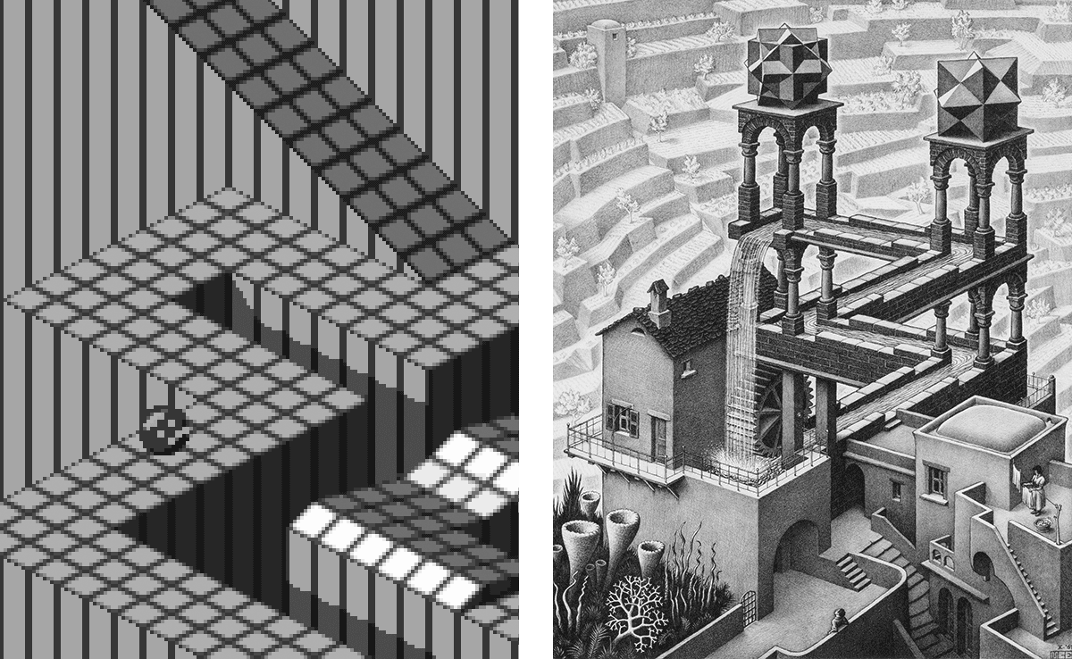
There may be a nostalgic element to that: The first technical drawing I saw was probably an instruction manual for a Lego kit (Fig. 5); isometric views’ enduring tenure in video game design began in the arcades of my youth (Fig. 6); and M.C. Escher’s mind-bending lithographs were among my most significant adolescent art obsessions (Fig. 7). However, I think there’s something more fundamental at work in the satisfaction I get from these images, something beyond the happenstance of what I was exposed to as a child.
Isometric projection is a form of parallel projection, a means of rendering three-dimensional objects in two dimensions. It differs from the naturalistic perspective you might see in a photograph in that objects maintain their size relative to each other rather than appearing larger or smaller relative to their distance from the viewer, and parallel lines remain parallel rather than converging on a vanishing point, hence the term “parallel projection” (Fig. 8).
Of the various forms parallel projection can take, the isometric version interests me most because the relationships between its three coordinate axes are all identical: The angle between any two of them is 120 degrees. In the case of a cube, this allows us to see each of its three visible planes in exactly equal measure. It also means an isometric grid is made of interlocking equilateral triangles, which is an irresistibly tidy means of representing a three-dimensional space (Fig. 9). (Some of the examples I cited earlier have slightly different angles and are therefore not technically isometric, but we won’t hold that against them.)
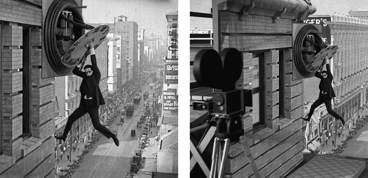
As perfect as it all seems, though, any two-dimensional rendering of a three-dimensional thing is inherently ambiguous, since there’s only so much we can know about an object or scene when viewing it from one fixed angle. And for as long as people have been making images, they’ve been finding creative ways to exploit that ambiguity. A classic example of this is in an iconic scene from the 1923 film Safety Last!, in which Harold Lloyd appears to be hanging precariously from the side of a building, high above a busy city street. In reality he’s hanging from a fake facade just a few feet above a padded platform on the building’s roof (Fig. 10).
Despite its orderly appearance, isometric projection is fertile ground for this sort of manipulation, particularly with simple geometric objects, since multiple interpretations of those objects and their spatial relationships to each other are often available to the viewer (Fig. 11). It’s also rife with opportunities for creating impossible objects that defy rational understanding (Fig. 12).
And so goes the seduction with isometric projection: Its idealized geometry suggests an accessible codification of objective reality, a shortcut to a structural understanding of an otherwise chaotic universe; and yet its idiosyncratic visual language is just as ambiguous and falsifiable as any other, perhaps even more so. Isometric projection is a beautiful lie, and one for which I can’t bring myself to fault the liar.
After spending some time experimenting with combinatorics in isometric space, I landed on a two-layered exploration, with each layer addressing, respectively, the beauty and the lie of isometric projection: 1) What are the various ways a distinct set of objects can be arranged in three dimensions within the regimented boundaries of a defined space? 2) What are the various ways those arrangements can be scrambled by the ambiguity of isometric projection?
For the first combinatorial layer, a 3×3×3 cube is the defined space—specifically the cube’s three visible surfaces—accounting for a total of 19 available units of space (Fig. 13). The objects meant to be arranged in that space are three blocks: a 1×1×3 block (let’s call it Block A, Fig. 14), a 1×2×2 block (Block B, Fig. 15), and a fusion of two 1×2×2 blocks joined at a 90-degree angle (Block C, Fig. 16). The three blocks collectively account for 13 units of space.
To find all the ways these blocks can be arranged, first assign a unique number to each of the 19 available units of space (Fig. 17). Next, find every possible position each individual block can occupy in that space, and name each position according to the numbered units it occupies. There are 15 possible positions for Block A (Fig. 18), 12 positions for Block B (Fig. 19), and six positions for Block C (Fig. 20).
Finally, start making arrangements of the three blocks, beginning by comparing each of Block A’s positions to each of Block B’s positions (Fig. 21). For each comparison, if the two positions share any numbers, that means they overlap, and the pair is disqualified. If they don’t overlap, the pair is put into a list, which will ultimately contain 111 valid pairs. Once the full list of valid Block A / Block B pairs is assembled, repeat the process again by comparing each pair to each of the Block C positions. As before, any arrangement with no repeated numbers is deemed valid. When all is said and done, 846 comparisons have been made between the three blocks, determining that they can be validly arranged 54 different ways.
At this point there appears to be a problem. The blocks in these arrangements may not overlap in theoretical three-dimensional space, but their two-dimensional isometric projections do. Every arrangement has at least one block partly obscured because another block is positioned between it and the viewer, which is to be expected. But the two-dimensional versions of the blocks are effectively flat decals, and while the system that generated their arrangements knows where to place each of them, it doesn’t know their correct stacking order, and that stacking order varies for each arrangement (Fig. 22). I could modify the system to solve this or manually edit all 54 arrangements, but I prefer to see this as an opportunity rather than a problem to solve, which brings us to the second combinatorial layer of this exploration: embracing the ambiguity of isometric projection.
Every arrangement consists of three blocks, which means one is in the back, one is in the middle, and one is in the front. And since there are three blocks, they can be sequenced six different ways: ABC, ACB, BAC, BCA, CAB, CBA. For each arrangement, one of those is the intended stacking order, rendering the scene appropriately within the boundaries of the established three-dimensional space. The other five stacks create alternate realities, disregarding the boundaries and changing the blocks’ spatial relationships (Fig. 23). This kind of scrambling of perception is a big part of what makes isometric space so fascinating to me, so the “incorrect” stacks should be considered every bit as vital to this exploration as the “correct” ones.
Six stacking orders for each of the 54 arrangements brings the total number of generated images to 324, but even though in theory they’re all unique, in practice some stacks look identical to others (Fig. 24). This is because the shapes of the blocks make it possible for them to avoid overlapping each other, making their arrangement look the same regardless of which is on top. Two thirds of the arrangements have two stacks that appear to be duplicates. Removing them brings the final total to 252 images.
The end result, for me, is both lucid and hypnotic, a sprawling portrait of the uncanny atmosphere of isometric space. The same compelling geometry that can bring such clarity to these 54 arrangements can also easily and indifferently distort them many times over. It’s an unreliable narrator who won’t shut up, and I can’t stop listening.
Rob Weychert
rob@robweychert.com
Visit the shop to buy this issue’s print edition or poster!